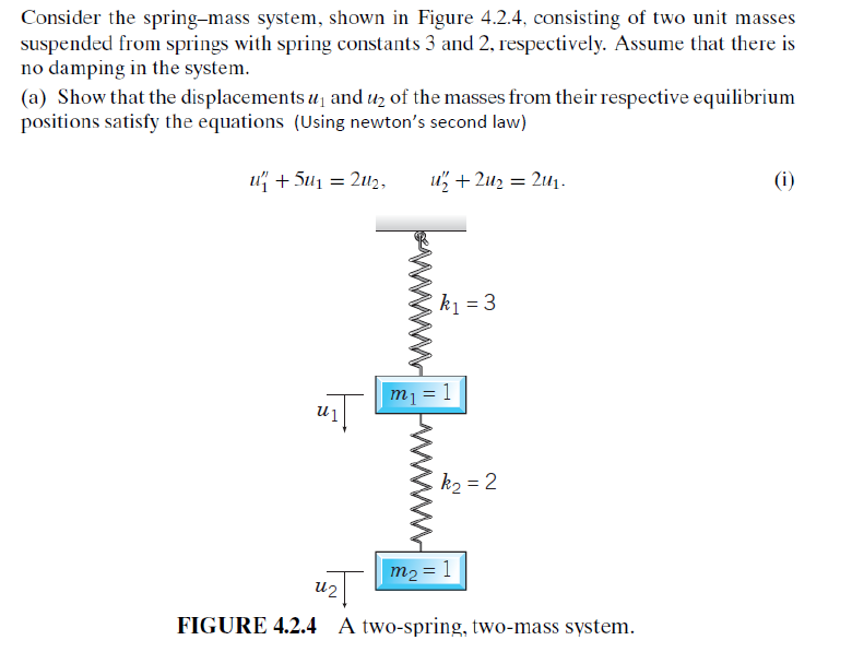
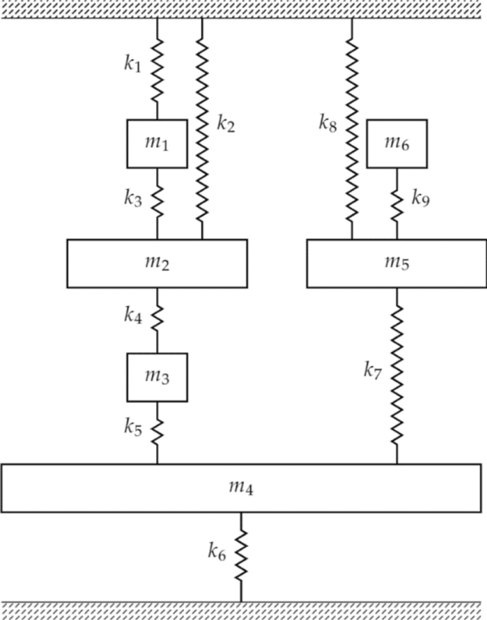
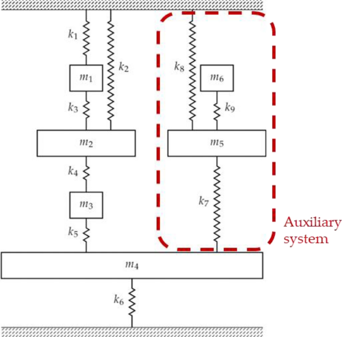
Consider The Spring Mass System Shown In Figure 424
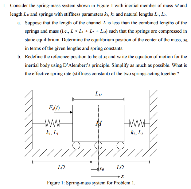
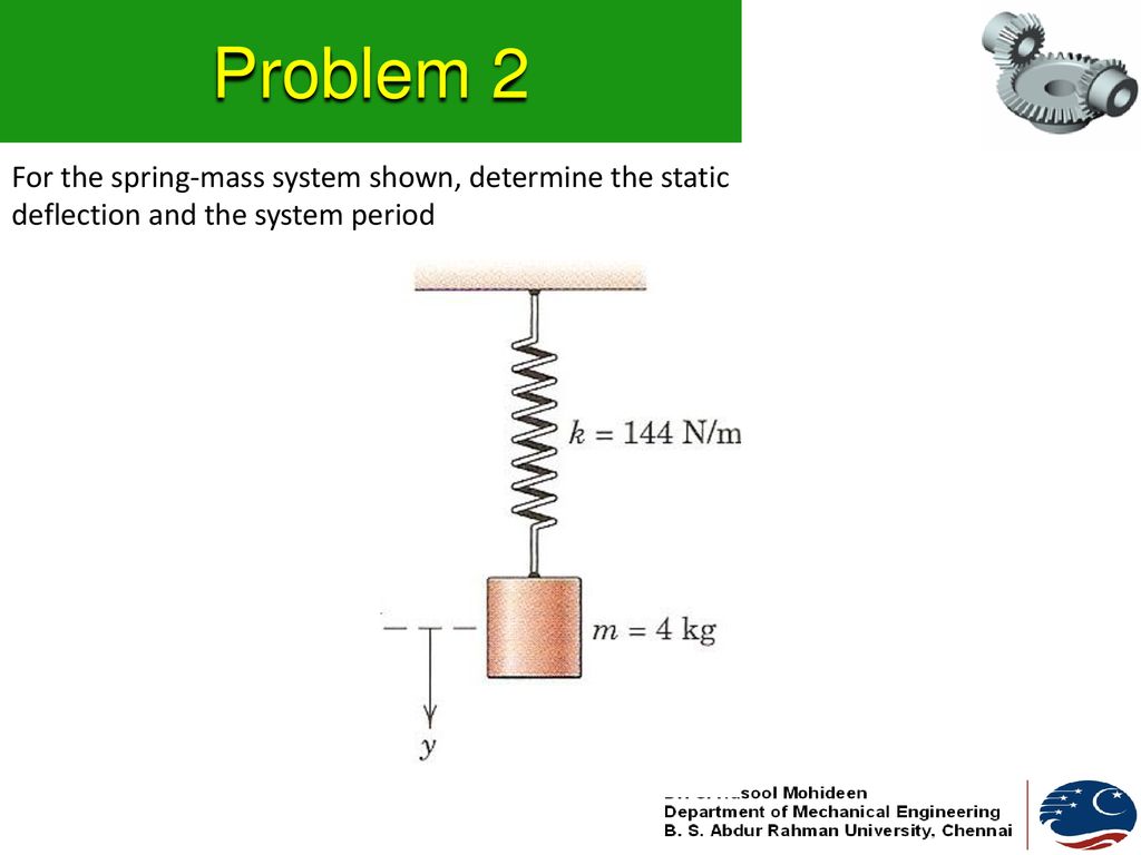
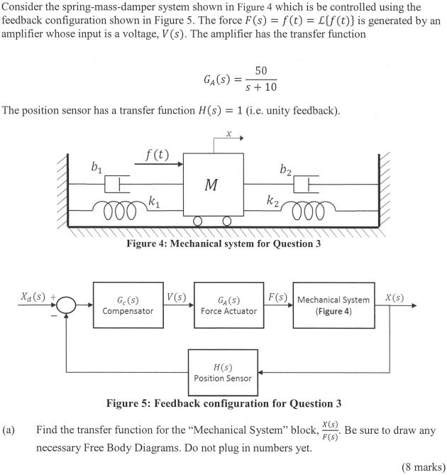
Consider the spring mass system shown in figure 424. 111 Consider the mass-on-a-spring system shown in the figure. But okay So far apart theyre here. The spring-mass system can also be used in a wide variety of applications.
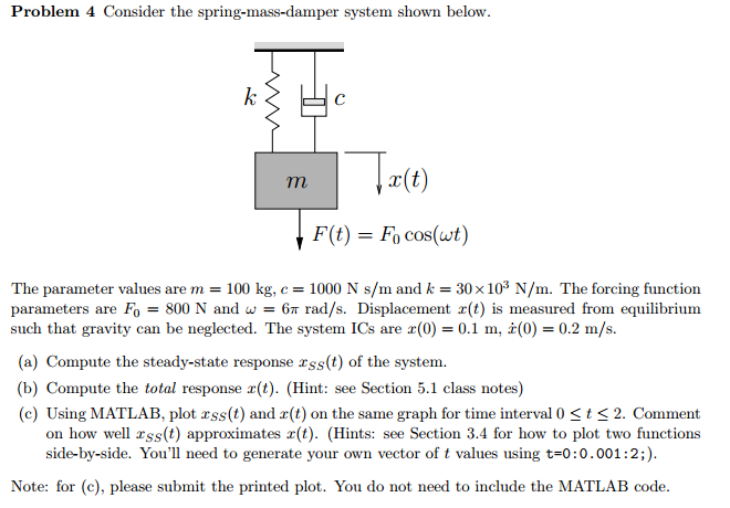
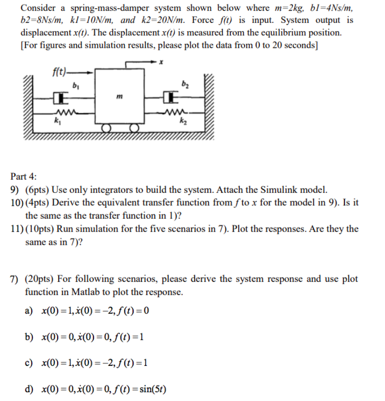
The mass m is supported by a spring of stiffness k and is excited by a dynamic force ft. Assuming no friction in the pulley find the maximum elongation of the spring. A spring-mass system in simple terms can be described as a spring sytem where a block is hung or attached at the free end of the spring.
The system shown in the figure consider of a light inextenslible cord light frictionless pulley and blocks of equal mass. The spring-mass system can usually be used to find the period of any object performing the simple harmonic motion. A mass m is suspended from a spring of stiffness 4000 Nm and is subjected to a harmonic force having amplitude of 10 N and a frequency of 5 Hz.
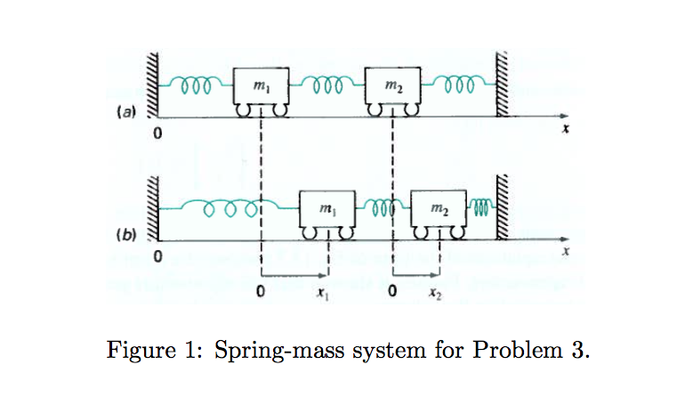
Assume that there is no damping in the system. Consider the spring-mass system shown in Figure 2. Consider the spring - mass system shown in Figure 424.
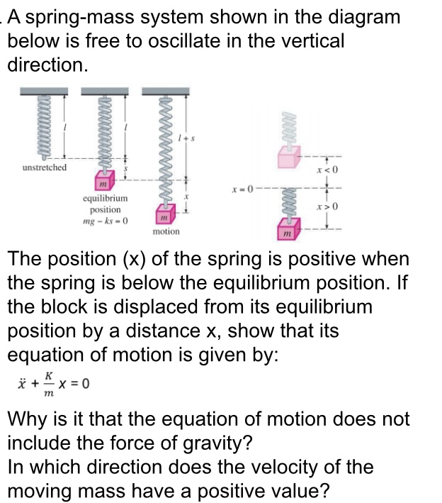
The spring-mass system of Question 4 It consists of a mass m attached to the lower free end of a spring as shown in Figure 3. Consider the spring-mass system shown in Figure 3 below. One Times Co sign of five p plus C.
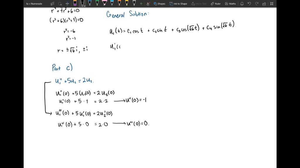
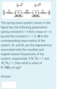
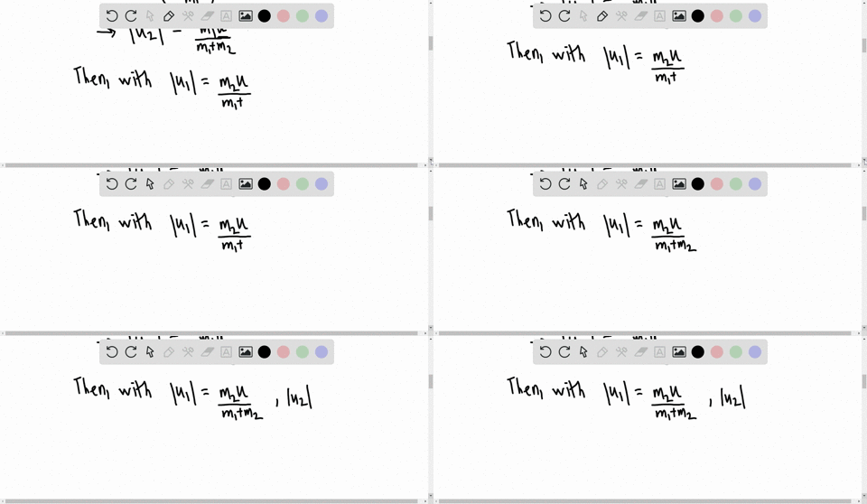
Consider the springmass system shown in Figure 424 consisting of two unit masses suspended from springs with spring constants 3 and 2 respectively. At the equilibrium position the spring is relaxed. Consider the spring - mass system shown in Figure 424.
In addition find the amplitude four cycles later. Let us find out the time period of a spring-mass system oscillating on a smooth horizontal surface as shown in the figure 136.
What is the frequency of this simple harmonic oscillator.
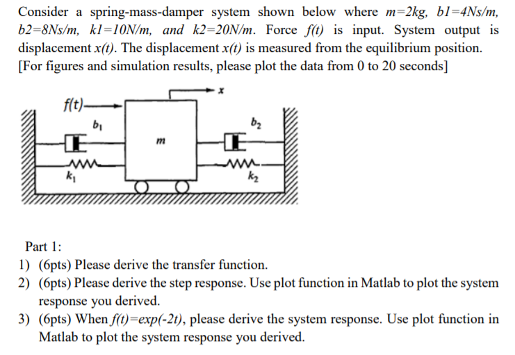
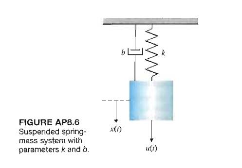
The basic vibration model of a simple oscillatory system consists of a mass a massless spring and a damper. The upper end of the spring is immovable and its mass is considered negligible. Initially the spring is unstretched when the system is released from rest. The spring-mass system of Question 4 It consists of a mass m attached to the lower free end of a spring as shown in Figure 3. A Show that the displacements u 1 and u 2 of the masses from their respective equilibrium positions satisfy the equations b Solve the first of Eqs. If the particle strikes thepan witha speed v find the speed with which the system moves just after the collision. The amplitude of the forced motion of the mass is observed to be 20 mm. Assume that there is no damping in the system. 4 pts b Assume the solution for each masssystem is of the general form it Ē A coswt B sinwt where ñ 1.
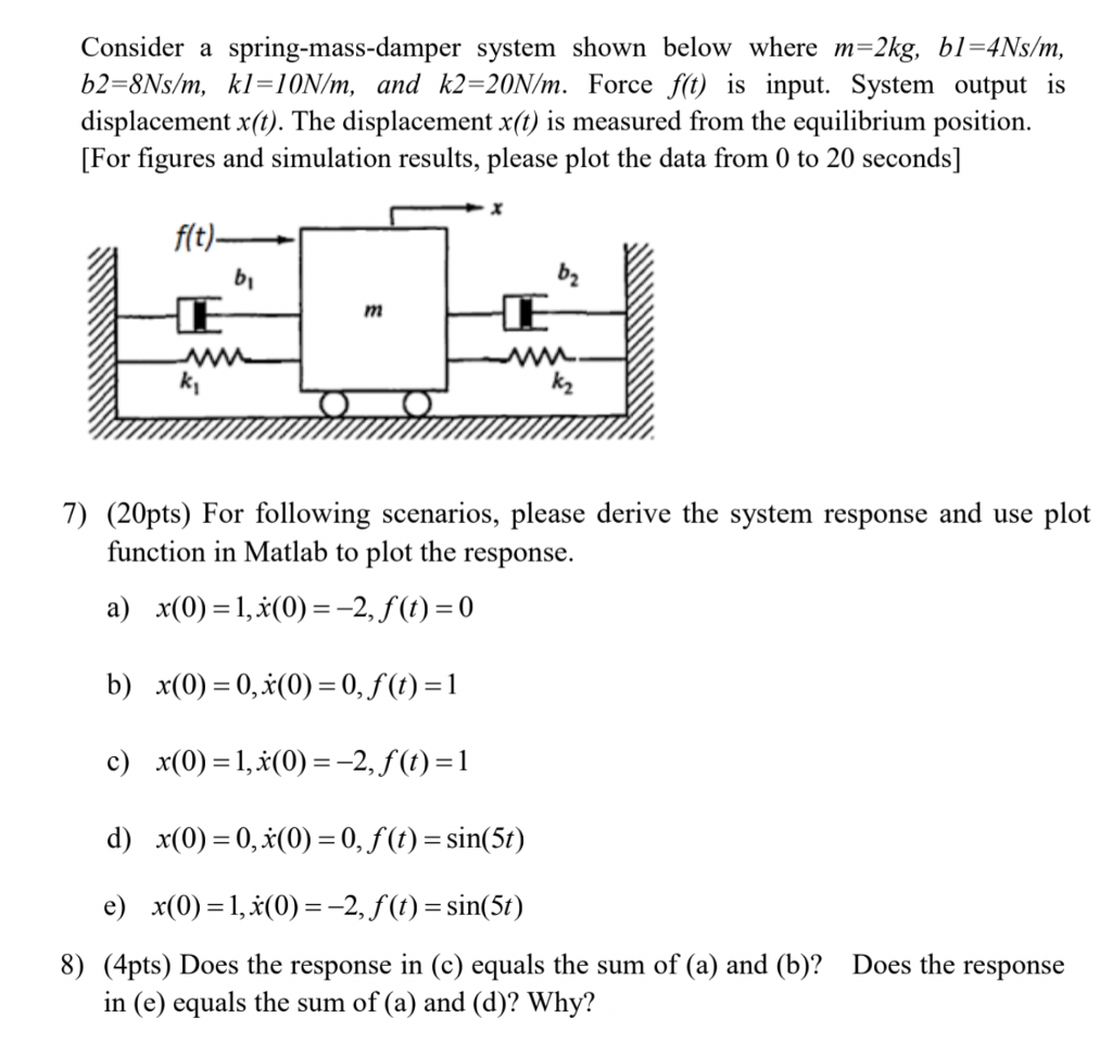
Assume that there is no damping in the system. Fyl kx R-bu F Focos wt mg Figure 3. A Show that the displacements u 1 and u 2 of the masses from their respective equilibrium positions satisfy the equations. In the system shown in Figure 5-59 the numerical values of rn b and k are given as rn 1 kg b 2 N-secm and k 100 Nm. 38 Hz Submit Answer Incorrect. Initially the systemis at rest when a particle of mass m falls on the pan and sticks to it. Mass-Spring-Damper Systems The Theory The Unforced Mass-Spring System The diagram shows a mass M suspended from a spring of natural length l and modulus of elasticity λ.















Post a Comment for "Consider The Spring Mass System Shown In Figure 424"